Introduction: Integrity Blind Spots in Modern RTK Networks
RTK networks have become a critical layer of infrastructure for applications requiring real-time, centimeter-level positioning. However, most RTK network operators still focus primarily on reference station availability — uptime, connectivity, and data flow — while leaving a major blind spot unaddressed: the integrity of the GNSS observations and the RTCM correction data itself.
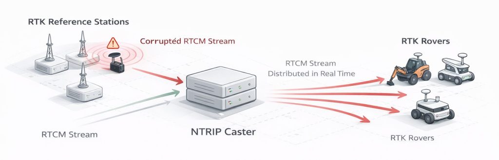
A reference station affected by GNSS interference can remain fully “operational” from a network perspective, continuously streaming RTCM corrections to hundreds of rovers. Yet those corrections may already be degraded or internally inconsistent. Low-power jamming can silently reduce signal quality without causing receiver outages. Spoofing can distort observables while preserving syntactically valid data streams. In both cases, corrupted corrections propagate downstream in real time, long before traditional availability alarms are triggered.
GP-Cloud addresses this gap by monitoring GNSS signal quality and analyzing RTCM correction streams in real time. Instead of treating correction data as inherently trustworthy, GP-Cloud evaluates its consistency, stability, and underlying signal conditions, detecting degradation and anomalies before they cascade through the RTK network.
For reference stations based on Septentrio chipsets, GP-Cloud supports the SBF protocol, enabling deeper analysis using raw observables and RF spectrum.
Learn more here: https://gpspatron.com/septentrio-gp-cloud-centralized-gnss-interference-monitoring/
The Cascade Effect in RTK Networks
RTK networks are structurally vulnerable to a single-point failure mode: one compromised reference station can instantly affect every connected rover. The propagation is automatic and immediate.
Low-power jamming may not fully suppress GNSS reception. Instead, it degrades signal quality while allowing the reference station to continue operating:
- Reduced C/N₀, increased pseudorange noise, unstable carrier-phase tracking
- RTCM corrections continue streaming, often without explicit quality flags
- Many rover implementations either ignore quality indicators or apply them inconsistently
As a result, rover behavior becomes unpredictable. Some receivers drop from RTK FIX to FLOAT or standalone mode. Others maintain RTK status while delivering degraded accuracy. The outcome depends on firmware logic, internal thresholds, and baseline length — not on a clear network-level failure signal.
Under spoofing, the situation is more severe and less deterministic:
- The reference station computes a false position or distorted observables
- Corrupted corrections are broadcast as valid RTCM messages
- Rovers combine false reference data with real satellite observations
This creates internally contradictory states that rover firmware cannot reliably resolve. Some receivers lose solution entirely, others output erratic coordinates, and some appear nominal while slowly drifting. There is no uniform failure mode, making detection based solely on rover-side behavior unreliable.
The critical distinction is that low power jamming often manifests as gradual degradation, while spoofing produces logically valid but fundamentally inconsistent correction data. In both cases, the network remains “up” while accuracy collapses.
Impact on Real-Time High-Precision Positioning Applications
Applications that depend on real-time, centimeter-level positioning are particularly exposed to this failure mode. Unlike post-processed workflows, real-time systems cannot validate results retrospectively or smooth errors over time. Any degradation in corrections immediately affects the position solution.
This impacts a wide range of RTK-dependent applications:
- Construction and machine control: systematic offsets, surface deformation, or oscillatory control behavior while the system still reports RTK FIX
- Precision agriculture: drifting guidance lines, degraded pass-to-pass accuracy, and cumulative errors across large fields
- Autonomous and semi-autonomous vehicles: unstable localization, sudden jumps, or loss of confidence in GNSS–IMU–LiDAR fusion
- Surveying and deformation monitoring: reference drift propagates directly into rover measurements, invalidating results without obvious alarms
- Port, rail, and industrial automation: positioning-dependent safety zones and control logic may be violated due to silent accuracy loss rather than total GNSS outage
The primary risk is not a clean failure, but false confidence.
Rovers continue operating in RTK FIX or FLOAT modes while ingesting corrupted corrections, producing plausible-looking coordinates with incorrect absolute or relative positioning.
In networked environments, this effect scales instantly. A single compromised reference station can affect hundreds of machines simultaneously, turning a localized RF disturbance into a system-wide operational fault.
This is why monitoring GNSS signal quality and RTCM integrity at the reference station level, rather than relying solely on availability and data flow, is essential for modern RTK networks operating in real-world interference conditions.
First Protection Layer: Real-Time RTCM Data Integrity Monitoring
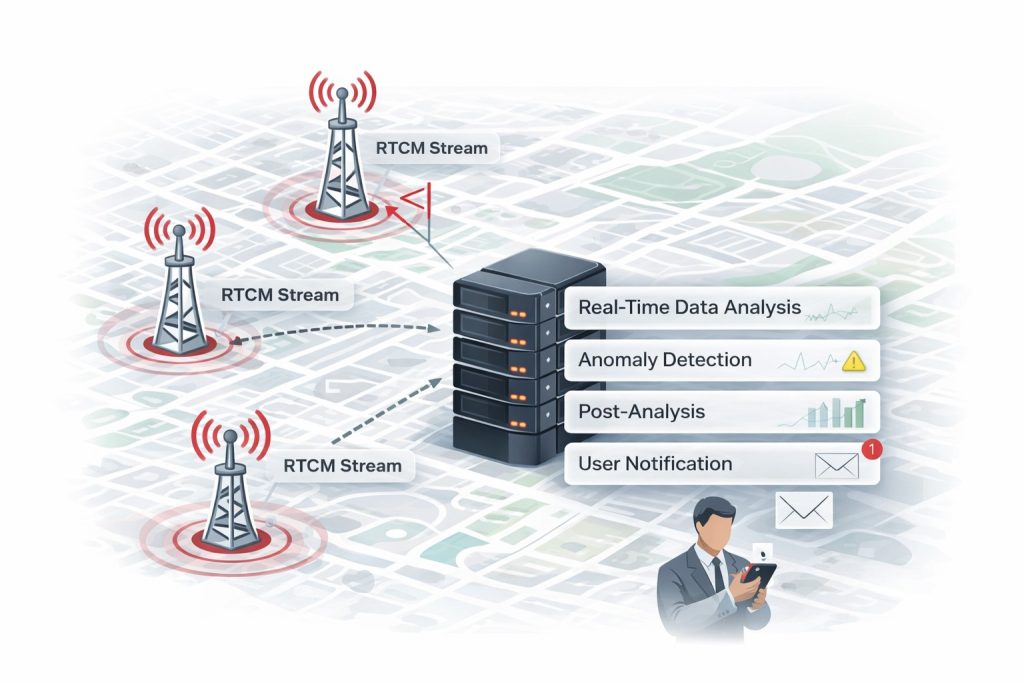
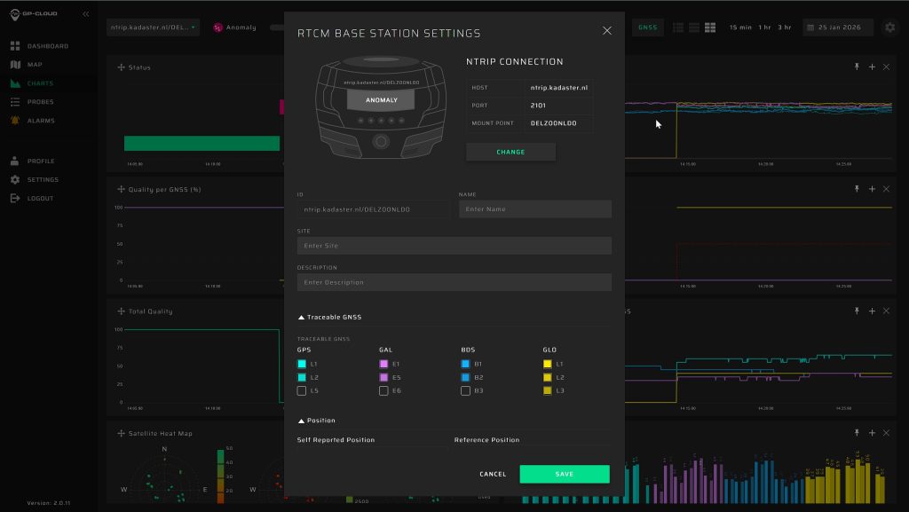
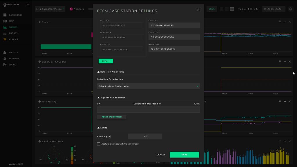
The first and most basic protection layer in GP-Cloud is real-time RTCM data integrity monitoring. Users can forward their RTCM streams to GP-Cloud via NTRIP and continuously monitor correction data quality.
When a new RTCM stream is connected, the user defines the reference position of the base station. This position is used as a baseline for RTCM consistency checks.
After that, the user starts the calibration process for the anomaly detection algorithms. The calibration runs for up to 24 hours and builds a statistical model of normal RTCM behavior for this specific reference station.
Anomaly detection starts immediately after calibration is initiated. Detection accuracy improves as calibration progresses and reaches optimal performance after the full calibration period. The calibration process can be reset manually at any time.
RTCM data monitoring is the most basic and easiest way to monitor the integrity of an RTK network. It requires no hardware installation, no receiver firmware changes, and no software upgrades on reference stations. The only requirement is to forward existing RTCM data streams to GP-Cloud, either to our cloud infrastructure or to an on-premises GP-Cloud deployment within the user’s own environment.
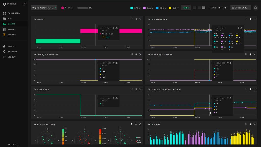
Despite its simplicity, this layer enables reliable detection of a wide range of anomalies in RTCM data, including:
- Silent degradation caused by low-power GNSS jamming
- Inconsistent RTCM data caused by spoofing
- Abnormal RTCM behavior that would otherwise propagate unnoticed through the network
When an anomaly is detected, GP-Cloud can notify operators in real time and provide immediate visibility into affected streams. In addition, GP-Cloud can be integrated with the user’s NTRIP caster software, allowing automated actions such as temporarily disconnecting or switching users away from a reference station where an anomaly has been detected.
By detecting anomalies directly in RTCM data streams, GP-Cloud prevents faulty data from silently cascading through the RTK network and affecting large numbers of connected rovers.
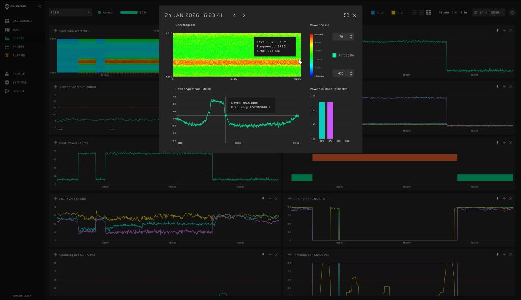
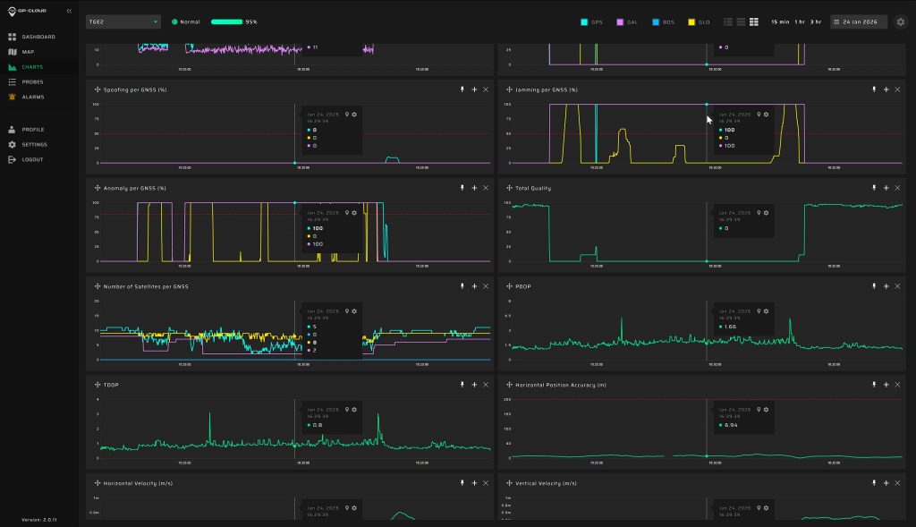
Second Protection Layer: GNSS Signal-Level Analysis with GP-Probe TGE2
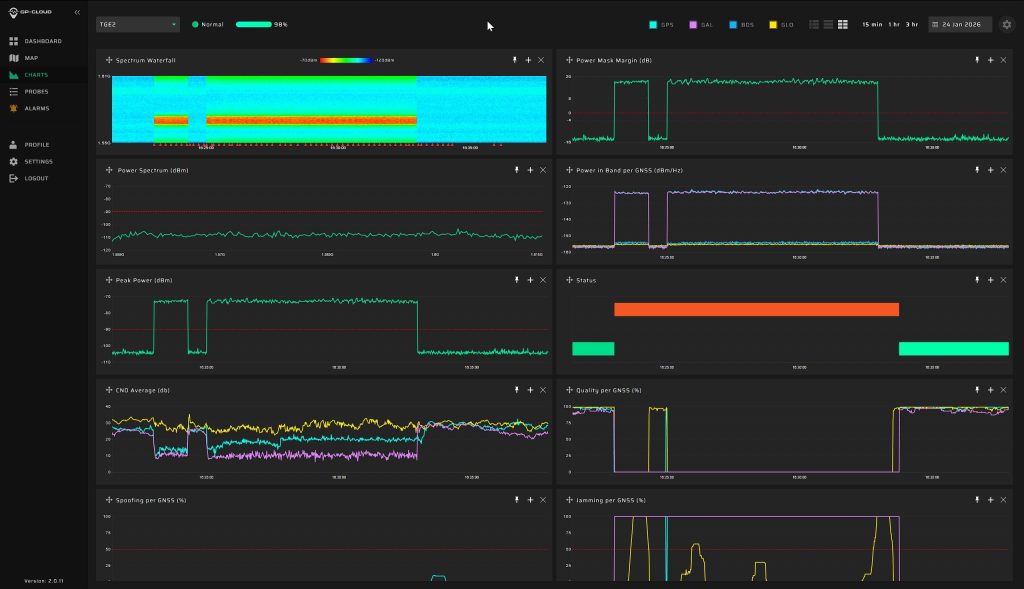
The second layer of protection is based on deploying a GP-Probe TGE2 sensor near the RTK reference station. This layer is required when deeper analysis is needed to identify the type of interference and understand its physical nature, rather than only detecting anomalies in RTCM data.
While RTCM monitoring detects abnormal behavior in data streams, TGE2 provides direct visibility into GNSS signals themselves. This enables reliable differentiation between:
- GNSS jamming (military-grade, low-cost jammer)
- Coherent and non-coherent spoofing (intentional, unintentional spoofing)
- Industrial RF interference
This level of analysis is essential for developing mitigation and response scenarios, such as locating and eliminating an industrial interference source or confirming a deliberate attack.
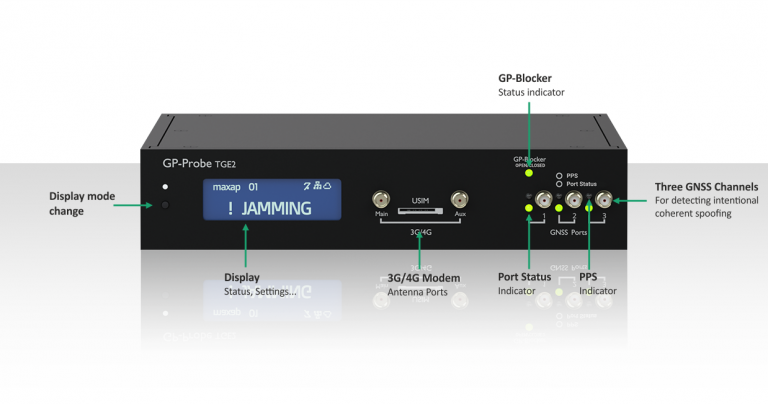
High-performance three-channel GNSS spoofing/jamming detector with advanced spectrum analysis capabilities.
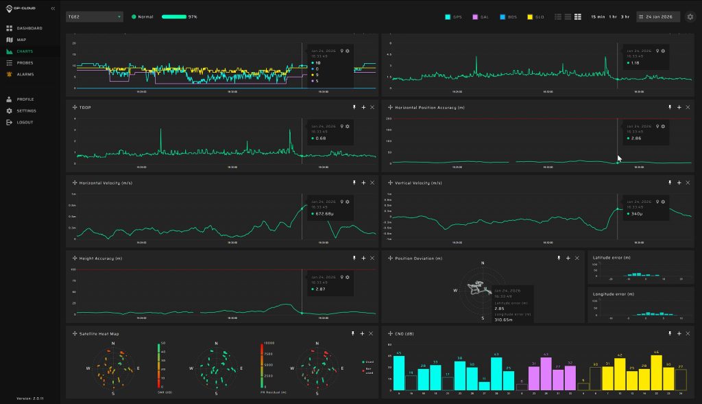
The TGE2 sensor is installed close to the reference station and requires three GNSS antennas. The multi-antenna configuration enables spatial signal analysis, which is critical for detecting and classifying advanced coherent spoofing scenarios. Compared to RTCM data, TGE2 provides significantly richer information, including raw RF and signal-quality metrics:
Third Protection Layer: End-to-End Correction Performance Validation Using a GNSS Rover (NMEA)
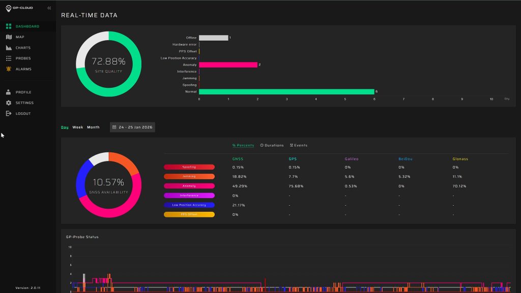
The third protection layer provides direct, end-to-end validation of correction performance by monitoring the positioning results produced using the RTCM data generated by the RTK network.
This layer is implemented by adding a GNSS rover to the network. The rover is connected to the correction stream of the selected reference station and continuously solves the navigation task using these corrections, exactly as a real user would.
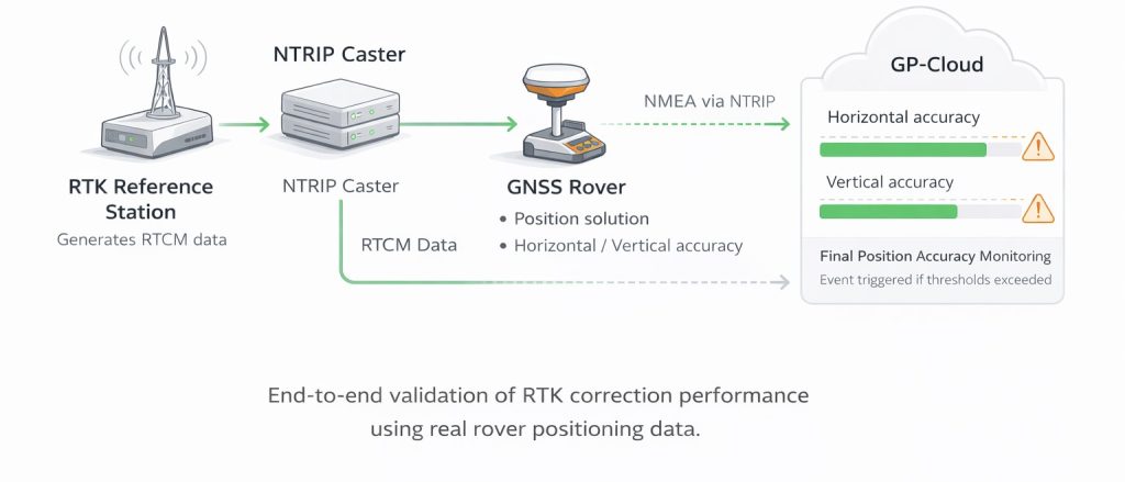
The rover then transmits its positioning data to GP-Cloud using the NMEA protocol over NTRIP. Based on this data, GP-Cloud monitors the actual positioning performance achieved with the corrections and evaluates whether it remains within defined accuracy limits.
Operators can configure event detection thresholds for:
- Horizontal position accuracy
- Vertical position accuracy
- NMEA data anomaly
If any of these parameters exceed the defined limits, GP-Cloud generates an event, providing immediate visibility into degradation of correction performance.

This approach delivers a final, practical confirmation that the RTCM data streams generated by the network meet the targeted accuracy requirements for a specific rover implementation. Since GP-Cloud supports the standard NMEA protocol, any GNSS receiver can be used as a rover, without vendor lock-in or specialized hardware.
This third layer represents the final level of protection, as it monitors the actual position solution obtained from the corrections. By continuously validating horizontal and vertical accuracy at the rover level, it provides the strongest possible assurance that the RTK network operates within its intended accuracy and performance limits.
On-Site Interference Localization with GP-Probe Nano
Once interference has been detected and its temporal patterns are understood (time of occurrence, duration, repetition), the next step is on-site localization of the interference source. For this purpose, GP-Probe Nano is used as a portable field tool.
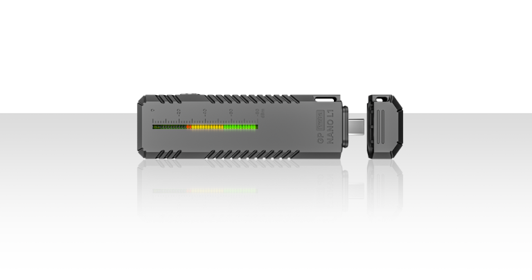
Ultra-compact wearable GNSS jamming detector for field use and source localization.
GP-Probe Nano is a compact, high-sensitivity GNSS interference power detector designed for on-site investigations. It allows operators to move directly within the affected area and analyze spatial changes in interference power in real time.
By monitoring received power levels while moving closer to or farther from potential sources, the operator can quickly localize the interference source.
This approach is especially effective when interference is caused by:
- Malfunctioning electronic equipment
- Industrial machinery
- Wi-Fi access points and wireless devices
- Surveillance cameras and video transmission systems
- Other unintended RF emitters operating near GNSS bands
Using GP-Probe Nano, operators can efficiently locate and remove local interference sources, restoring GNSS signal quality without extended investigations or complex measurement setups.
Ready to Protect Your RTK Network?
GPSPATRON offers a complete set of tools for monitoring, analyzing, and protecting RTK networks—from RTCM data integrity monitoring and GNSS signal analysis to on-site interference localization.
Our solutions integrate easily with your existing infrastructure and software, including NTRIP casters, and adapt to your operational requirements without disruptive changes.
If you are dealing with GNSS interference or want to proactively strengthen your RTK network, get in touch with us. We’ll review your setup, discuss your challenges, and help you design the right monitoring and protection strategy for your project.
